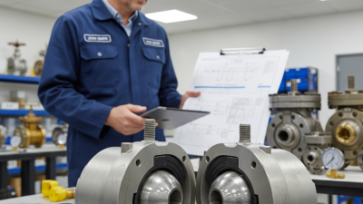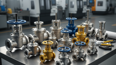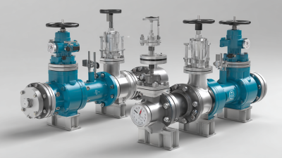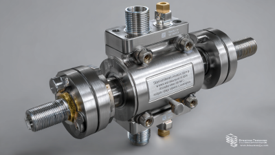
A screwed ball valve is a compact shutoff device with threaded connections at both ends. It controls fluid flow through a quarter-turn rotating ball. When the handle aligns with the pipe, the ball’s bore opens. Turn the handle ninety degrees, and the solid side blocks the passage.
Valve engineer Robert W. Hunt explains, “A ball valve works best when its sealing surfaces remain clean, aligned, and properly supported.” This practical observation matters in real installations. A small valve may look simple, yet pressure, temperature, thread quality, and material selection affect its service life. Screwed Ball Valves are commonly installed on water lines, compressed-air systems, fuel services, and many process connections. Their threaded design allows quick installation without welding equipment. It also makes replacement easier in tight mechanical rooms.
The body may use brass, stainless steel, carbon steel, or engineered plastic. The ball often uses chrome-plated brass or stainless steel. Soft seats create tight shutoff, but they may wear under abrasive flow or excessive heat. Do not force the handle. That mistake can damage the stem or seat.
A careful installer checks thread compatibility, flow direction, sealant choice, and operating pressure. Leaks often begin at poorly cut threads or over-tightened joints. The valve is not maintenance-free. That deserves attention.
This article examines what a screwed ball valve is, how its internal parts work, and where Screwed Ball Valves fit within modern piping systems. It also considers their strengths, limitations, and the practical details that determine reliable performance.
A screwed ball valve is a shut-off valve with threaded connections at both ends. “Screwed” describes the connection method, not the internal ball. Inside the valve body, a drilled ball rotates around a stem. When the bore aligns with the pipe, fluid flows through. A quarter-turn closes the passage and blocks flow. Simple and quick.
Its basic features include a valve body, ball, stem, seats, and threaded ends. The seats press against the ball to reduce leakage during operation. Common body materials include brass, stainless steel, and carbon steel. Seat materials must match the fluid, temperature, and pressure conditions. A valve rated for water may not suit hot oil or aggressive chemicals. That detail is easy to overlook.
In field inspections, technicians often check thread condition, handle movement, and signs of seepage. Clean, undamaged threads help create a dependable joint. Sealant or suitable thread tape may be required, but excessive material can enter the flow path. Installation should avoid twisting the valve body or using the handle as a wrench. That mistake happens. A screwed ball valve usually works best in fully open or fully closed positions. Partial opening can damage seats through high-velocity flow. It is compact and economical, yet it is not maintenance-free. Even a well-made valve needs correct selection, careful installation, and periodic inspection.
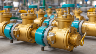
A screwed ball valve uses threaded ends to connect with compatible pipes or fittings. Its compact body usually contains a polished ball with a central bore. When the bore aligns with the pipeline, fluid can pass through. A quarter-turn rotates the ball ninety degrees and blocks the flow. It is simple and fast.
The valve body holds pressure and protects the internal parts. The ball controls the opening position. Stem seals prevent fluid from escaping around the rotating stem. Seats press against the ball and create the main shutoff seal. A handle transfers manual force to the stem, while an actuator can provide automatic movement. Packing or additional sealing rings may support the stem area.
In practical inspections, thread damage often causes trouble before the ball fails. Sealant must suit the fluid, temperature, and pressure. Excessive tightening can distort the body or damage the threads. Small errors matter. The valve should be installed with correct flow direction when specified by its design. Before maintenance, isolate and depressurize the line completely. A valve that feels stiff may have debris, pressure imbalance, or worn seats. Do not force it blindly. Checking torque, leakage, and thread condition gives a more reliable assessment. Some installations still need improvement because operators may treat a shutoff valve as a flow-control device, which can accelerate seat wear.
A screwed ball valve uses threaded ends to connect with matching pipe threads. Inside, a drilled ball controls the flow path. The operating sequence is simple. Turning the handle rotates the stem. The stem turns the ball through ninety degrees. When the bore faces the pipe, fluid passes with little resistance. When the solid side faces the opening, flow stops. Soft or metal seats press around the ball and limit leakage.
In practical use, the handle position gives a quick visual signal. A handle aligned with the pipe usually means open. A crosswise handle usually means closed. The movement should feel firm and even, not forced. A stiff turn may indicate contamination, pressure imbalance, or damaged seals. I have found that installers sometimes overlook thread alignment. Cross-threading can damage the connection before the valve ever operates. The valve also works best as a shutoff device. Partial opening may cause turbulence and faster seat wear.
Tips:
Confirm the pressure and temperature ratings before installation. Clean both threads carefully. Apply a compatible thread sealant, but keep it away from the valve opening. Tighten the connection without excessive force. Test slowly after installation and check every joint for seepage. Always release system pressure before inspection. One detail is easy to miss: a closed handle does not prove zero pressure downstream. Verify the line condition with suitable instruments.
A screwed ball valve uses threaded ends instead of flanges or welded joints. Turning the stem rotates a drilled ball inside the body. When the bore aligns with the pipe, fluid flows. A quarter-turn closes the passage.
Common connection types include NPT, BSPT, and BSPP threads. NPT uses a tapered profile, while BSPP is typically parallel. These systems are not automatically interchangeable. ASME B1.20.1 and ISO 7-1 define different thread requirements, so checking the pipe and valve markings matters. A mismatched thread may feel tight but still leak.
Installation needs clean, undamaged threads. Apply a compatible sealant or thread tape to the male thread only. Keep the first thread clear. Tighten the valve with a wrench on the body, not the handle. Excessive force can distort the body or damage the seat. Install a union when regular removal is expected.
The U.S. Department of Energy reports that compressed-air leaks can waste 20–30% of system output, according to its compressed-air performance guide. That figure concerns air systems, but it shows why small connection leaks deserve attention.
Tips: Support nearby piping before tightening. Pressurize slowly, then inspect every joint. A dry surface is easier to judge. Field practice is rarely perfect; thread tape can hide poor engagement, so visual checks alone are not enough. Test according to the project specification and relevant valve standards, such as API 598 or ISO 5208.
A screwed ball valve uses threaded ends to join with matching pipe fittings. Inside, a drilled ball rotates a quarter turn between open and closed positions. When the bore aligns with the pipe, fluid passes with little resistance. Turn the handle 90 degrees, and the solid side blocks the flow. The design is simple, but proper installation still matters. Clean threads, suitable sealant, and correct tightening help prevent small leaks.
These valves suit water lines, compressed air systems, irrigation equipment, and many general industrial services. They are useful near pumps, tanks, and maintenance points where fast isolation is important. A technician can often install one with ordinary tools, without welding or special machinery. Their compact body also fits crowded pipe runs. Full-bore models usually create minimal pressure loss. That can reduce energy waste in frequently used lines. Still, “easy to install” does not mean maintenance-free.
A screwed connection may loosen under vibration or repeated temperature changes. Thread damage can also make removal difficult. The valve should not normally control flow halfway open, because turbulence can wear the seats and ball. Dirty media may scratch sealing surfaces, especially in small valves. Pressure, temperature, thread type, and sealing materials must match the service conditions. A valve rated for water is not automatically suitable for every fluid. In field work, selecting the cheapest option can seem practical. Sometimes it creates the most expensive leak later. Threaded valves are dependable for many moderate-duty applications, but welded or flanged designs may be safer for severe service.
| Data Dimension | Typical Information | Technical Notes and Practical Considerations |
|---|---|---|
| Valve Definition | Quarter-turn isolation valve with threaded pipe connections | A screwed ball valve uses a drilled and polished ball to control flow. The valve is normally opened or closed by rotating the ball through 90 degrees. |
| Connection Type | Female threaded, male threaded, or male-to-female threaded ends | Common thread standards include NPT, BSPP, and BSPT. The valve thread must match the pipe thread standard, size, and sealing method. |
| Common Nominal Sizes | Approximately DN8 to DN100; about 1/4 in to 4 in | Threaded ball valves are most frequently used in small and medium pipework. Available sizes depend on the design, pressure class, and applicable standard. |
| Flow Control Principle | Rotating ball with a full or reduced bore | When the bore aligns with the pipeline, the valve is open. When the ball turns 90 degrees and the solid side faces the flow path, the valve is closed. |
| Operating Position | Fully open or fully closed | The handle position usually indicates the flow path: parallel to the pipe means open, while perpendicular to the pipe means closed. |
| Actuation | Manual lever handle; optional electric or pneumatic actuator | Manual operation is common for small valves. Automated actuation may be used where remote control, sequencing, or frequent operation is required. |
| Typical Body Materials | Brass, bronze, stainless steel, carbon steel, or engineering plastics | Material selection depends on fluid compatibility, temperature, pressure, corrosion exposure, and installation environment. |
| Typical Seat Materials | PTFE, reinforced PTFE, or other engineered polymers | Soft seats provide reliable shutoff for many clean fluids, but their temperature and chemical-resistance limits must be checked before selection. |
| Typical Pressure Range | Often approximately 10 to 40 bar, depending on design | This is a general market range, not a universal rating. The maximum allowable pressure must be verified from the valve's pressure class and temperature-rating data. |
| Typical Temperature Range | Approximately −20°C to 180°C for many soft-seated designs | Actual limits vary significantly with body, seat, seal, and fluid materials. Higher-temperature service may require metal seats or a different valve design. |
| Flow Capacity | High for full-bore designs; moderate for reduced-bore designs | A full-bore passage minimizes pressure loss and supports pigging in some systems. A reduced bore is often more compact and economical but creates greater flow resistance. |
| Shutoff Performance | Typically strong Bubble-tight shutoff is possible | Performance depends on seat condition, ball finish, fluid cleanliness, operating pressure, and the applicable leakage standard. It is not guaranteed for every design or service. |
| Typical Applications | Water, compressed air, gas, fuel, irrigation, and general utility piping | They are commonly installed in plumbing branches, instrument-air lines, process skids, equipment isolation points, and low-to-medium-size utility systems. |
| Best-Suited Service | Clean or moderately clean, non-abrasive fluids | The compact quarter-turn design is well suited to isolation duties. Clean operating conditions help protect the ball and seats from scoring and leakage. |
| Primary Benefit | Fast operation 90-degree actuation | Compared with multi-turn valves, a quarter-turn mechanism can reduce operating time and simplify emergency shutoff. |
| Additional Benefits | Compact, lightweight, low maintenance, and comparatively low flow resistance | Threaded construction can simplify installation in small pipework and may avoid welding or flange alignment during assembly. |
| Installation Requirement | Correct thread engagement and suitable thread sealant | Use a compatible sealant or sealing tape where permitted. Avoid excessive tightening, which can damage the valve body, distort threads, or cause leakage. |
| Maintenance Requirement | Periodic inspection; usually no routine lubrication for sealed designs | Check for external leakage, stiff operation, corrosion, handle damage, and signs of seat wear. Follow the manufacturer's maintenance instructions for the specific valve. |
| Limitation: Throttling | Not ideal for continuous throttling | Leaving the ball partially open can produce turbulence, vibration, erosion, and accelerated seat wear. Use a valve designed for control service when precise flow regulation is required. |
| Limitation: Contamination | Sensitive to debris | Dirt, scale, welding residue, and abrasive particles can damage soft seats or prevent complete closure. Pipework should be cleaned or flushed before commissioning. |
| Limitation: Thermal Expansion | Cavity pressure may require attention | A closed ball can trap fluid in the body cavity. If the trapped fluid is heated, pressure may rise; pressure-relief or cavity-relief provisions may be necessary for specific services. |
| Limitation: Large Pipe Sizes | Less practical as size and torque requirements increase | For larger pipelines, flanged, welded, or wafer-style valve designs may provide more suitable mechanical strength, installation flexibility, and maintenance access. |
| Safety Consideration | Select according to fluid hazard, pressure, temperature, and applicable codes | Do not use a valve solely because its size matches the pipe. Verify material compatibility, fire-safe requirements, electrical classification, pressure rating, and local installation regulations. |
| Selection Checklist | Size, thread standard, pressure, temperature, media, bore, seat, body, and actuation | A correct selection balances shutoff performance, service life, installation constraints, operating frequency, and total lifecycle cost. |